
Using Override Driving WCS in Fusion 360, and Making It Better
Fusion 360 has this feature called “Override Driving WCS” when creating a probing action. What this allows you to do is to use a static point, like a vise corner, and probe the stock with a reference to a different work coordinate system (WCS). The Fusion 360 Guru Richard has done a great explanation on how to use it (found here https://youtu.be/X4qCU0X1pWM ) but it’s a bit light on the technical details and how it is actually implemented. That’s what I will attempt to do here and then improve upon it.
And before we get much further, the goal of using this feature is to: compensate for the actual stock position, and not do it manually
There were some questions, confusions, and comments on Richard’s video which I think show some confusion around how the Override Driving WCS actually works. My expectation, and some others, was that when you select your static point and then the WCS to be updated, the CAM would output in the new WCS. And it does that, technically speaking. It, however, isn’t done the way one might expect it to.
As an example we will use the below Fusion CAM template to explain what actually happens when you select WCS override. We’ll use our Haas TM3P as well.


In the example setup we have two important WCS points, G54 and G59. As explained by Richard in his video, G59 is the static point that does not change, i.e., the vise, and G54 is the stock position to be updated. And we also have the test setup in our Haas.
When creating the setup in Fusion, we select the G59 point as the WCS Origin and we also set “Work offset=1”. More on this in a minute.
Next we create a probing routine and we select the stock’s Z-Face to create a Z surface probe and a X-Y web probe operations. When selecting the probing cycles select the “Override Driving WCS” and enter ‘6’ for the G59 WCS.
Below is what an example of the Fusion 360 output Post for these operations.
N10 G59
N20 G01 X0.0 Y-2.25 F400 (move to part EXPECTED center in reference to G59)
... (turn on probes, and protected moves)
N30 G65 P9812 Z1.5 X5.5 R0.5 Q0.5 S1  (Measure X web, save to WCS=1 'G54' )
N40 G65 P9812 Z1.5 Y4.5 R0.5 Q0.5 S1  (Measure Y web, save to WCS=1 'G54' )
... (turn off probe and protected moves)
Line N20 and the subsequent lines are important to understanding what is actually happening on the machine side. Because we selected the G59 point in our model, then defined the setup to use “Work offset=1” we need a way to connect G54 to G59. That’s why it is necessary to use Override Driving WCS in the probing operations to get the ACTUAL center of the stock.
As a note: If we didn’t do any probing through fusion, and only our G59 had been defined in the machine this would most likely result in a crash. And not to get too side tracked, if we omitted the probing cycles and used “Work offset=6” in the setup menu without probing, the tools paths would work just fine Except, if our stock was oversized, out of position, etcetera we may not fully clean up the material, or have excessive tool load.
Line N20 is “X0.0 Y-2.25” that’s the expected center point from G59 that we selected in our model, and is a prerequisite for using the macro. Line N30 and N40 are the Renishaw probing macros for the "nominal size of feature" in X or Y axis. That’s important, we are not measuring the center of the part, we are measuring the nominal size of feature and thus the error from center. Below is a snippet from the Renishaw guide on probing macros.


So let’s just run the code and see what happens, below are two pictures, one of G54 with all zeros, and G54 after running the probing cycles.


Looking at the work offsets, something seems a little strange, right? Well yes, but no.
Let’s look at the differences from G54 and G59:
| G Code | X Axis | Y Axis | Z Axis |
| G54 | -20.1018 | -7.0640 | -15.2138 |
| G59 | -20.0645 | -7.0688 | -15.2115 |
| Difference | -0.0373 | 0.0048 | -0.0023 |
Based on where we probed, those WCS values don’t seem correct for G54, right? We selected the center of the stock as the zero point, but we only moved a few thousandths in X, Y, or Z on the offset page. So what gives? Before we answer that, lets post the drill operation.
... (switch to drill and set tool height)
N50 G54 (Actual WCS)
N60 G00 Z2.215 (assume this is 0.2 above stock)
N70 G01 X0.0 Y-2.25 (move to the EXPECTED center position from G59, and compensated by G54)
N80 G81 Z1.5 F20.0 (drill cycle)
What Fusion has done, perhaps unintuitively, is that it is still posting the tool path as based on the theoretical G59 stationary position we selected in the setup model. But the important thing to take away here is that it posted those tools paths with G54! So what that means is we don’t have to modify all the XYZ positions in all the tools paths, we just change the offset we use. This is unintuitive, and isn’t what’s expected, however, the only reason I can see why it’s implemented this way is because it’s easy. Why regenerate all the tool paths with adding the difference in position between G54 and G59 AND the actual part position, when you can just move one point?
With that said, the tools paths are correct and they will work using the method outlined by Richard in his tutorial video. It is however, unintuitive, and not what one might expect. And for all intents and purposes, it operates more similarly to using G52 offsets since the definition of the WCS isn’t changed. If you’re like me you want something different.
How do we make it better? First let’s define what “better” is.
Better is meeting our expectations when probing the stock center point will result in G54 being updated to the stock center point.
Ok, great, why? For me it helps in readability and checking heights, and subsequent operations. When the tool list is written with the “ZMIN” value I can use a caliper or scale to check that from the top of my stock, just as a sanity check. That’s not easily done in the prior example. If you have a subsequent operation that needs to be at the center of the part, or you take the part out of the vise, that G54 isn’t located at the part center. And if you didn’t know how the previous example really worked and absent-mindedly manually reprobed the center of the stock in G54 you would definitely get a crash condition.
To solve this we’ll still use G54 and G59, and we will still not have to manually probe the part, and we will also use a single point to change the program.
I like using the “part place holder” CAM templates so that I don’t need to create a CAM setup inside each part. It’s a very helpful method in a job shop environment. See the following videos for reference: https://youtu.be/FOQmAMzWMgQ https://youtu.be/W8l0nr146-4
Since I use a parameterized CAM template for my parts it gives me some helpful parameters to use. Shown below:
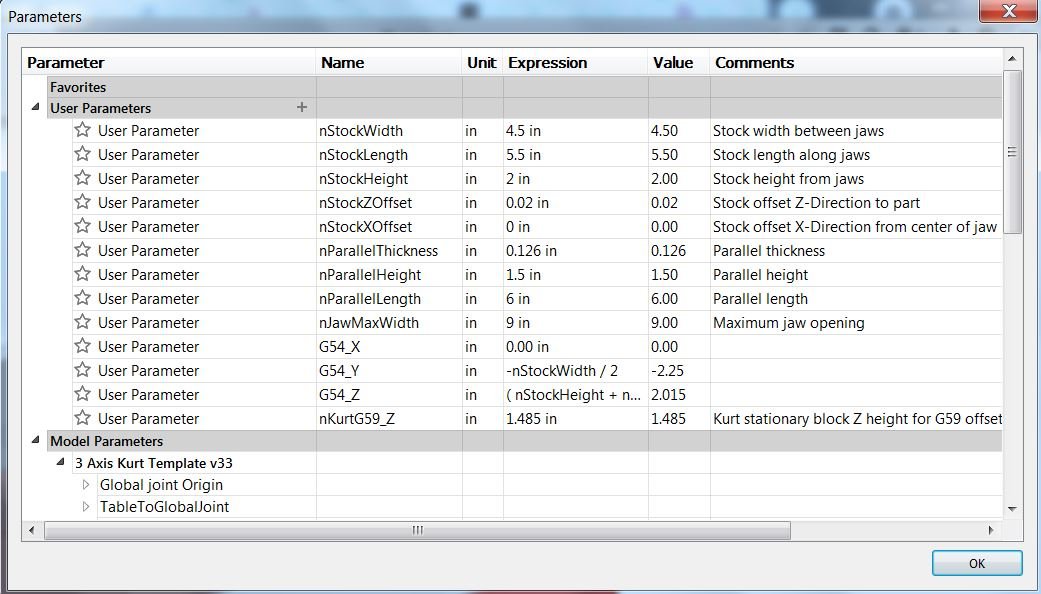
Since I have access to these parameters I can make a few expressions to calculate the distance from my G59 to the G54 stock center. Shown by parameters G54_X, Y, Z. Now I have a distance from my G59 point to my G54 point. What this allows me to do is to use the Haas variables for the G54 and G59 work offsets, and add my Fusion parameters to get the expected center point of G54.
#5221-#5226 G54 Work offsets X, Y, Z, A, B, C
#5321-#5326 G59 Work offsets X, Y, Z, A, B, C
Now for all intents and purposes we could simply write the following expression manually with “Manual NC” and “Pass through” operation:
N20 #5221 = #5321  +  [ 0.0  ]
N25 #5222 = #5322  +  [ -2.25]
N30 #5223 = #5323  +  [ 2.015]
What’s happening here is that I am updating G54 X, Y, and Z with the G59 X, Y, and Z coordinates and the user parameters such that G54 is now located at the center of the stock. When passing this code through the machine the work offsets are now:
| G Code | X Axis | Y Axis | Z Axis |
| G54 | -20.0645 | -9.3188 | -13.1965 |
| G59 | -20.0645 | -7.0688 | -15.2115 |
| Difference | 0.0000 | -2.250 | 2.0150 |
This now aligns with our expectations, that the G54 work offset is located at the center of the part.
I should note that doing it this way means that in the setup page you would select the G54 point as the WCS Origin, and NOT the G59 point. And then set “Work offset=1”.
So let’s take it one step further. Manually entering these values for every job would be a hassle and error prone, that’s where Fusion’s API comes in! For all the issues and quirks I have with Fusion, and all those tasks which seem trivial in other programs but not Fusion, scripting is the next best thing. And API scripting is just a fancy way of saying macro in layman’s terms.
It actually super easy to get started with scripting in Fusion, the Autodesk API user manual is a surprisingly helpful starting point, especially when compared to the help forum. Below is the script I wrote to do this for me automatically.
I won’t go into great depth here as I am not an expert, and I’m sure there’s a better way, however, the gist is:
Get the user parameters which contain the offsets calculated
Convert the user parameters from the default centimeters unit to inches for the case of my Haas
Round the conversion to 4 decimal places
Build the string that will be put into the “Manual NC” message pass through
Find the “Manual NC” operation and modify the message with the string built from before
Done!
Now I can simply press “Run script” in the manufacturing workspace, and the “Manual NC” will be updated with the expected G54 position. And when I run the probing macros, I DO NOT use “Override Driving WCS”.
This means that after the probing cycle, the output NC program is in reference to the stock center (G54), instead of the distance from G59 and subsequent errors stored in G54.
So now the NC code looks as we expect, and we can re-use G54 as the part center.
And obviously, use at your own risk, test your own code before you run it, I’m just a dude on the internet.
#Author-BWS
#Description-Update the G54 WCS from the static G59 position

import adsk.core, adsk.fusion, adsk.cam, traceback
import math

#Haas macro variables
stVarG54_X = "#5221 "
stVarG54_Y = "#5222 "
stVarG54_Z = "#5223 "

stVarG59_X = "#5321 "
stVarG59_Y = "#5322 "
stVarG59_Z = "#5323 "

def run(context):
    ui = None
    try:
        app = adsk.core.Application.get()
        doc = app.activeDocument
        products = doc.products
        product = products.itemByProductType('DesignProductType')
        design = adsk.fusion.Design.cast(product)
        unitsMgr = design.unitsManager
        ui=app.userInterface

        #design = adsk.fusion.Design.cast(app.activeProduct)

        #Get the offset from G59 to G54 from the design environment

        nG54_X = design.allParameters.itemByName('G54_X').value
        nG54_Y = design.allParameters.itemByName('G54_Y').value
        nG54_Z = design.allParameters.itemByName('G54_Z').value

        nG54_X = unitsMgr.convert(nG54_X, "cm","in")
        nG54_Y = unitsMgr.convert(nG54_Y, "cm","in")
        nG54_Z = unitsMgr.convert(nG54_Z, "cm","in")

        nG54_X = round(nG54_X,4)
        nG54_Y = round(nG54_Y,4)
        nG54_Z = round(nG54_Z,4)

        stG54_X=str(nG54_X)
        stG54_Y=str(nG54_Y)
        stG54_Z=str(nG54_Z)

        #Build the NC macro
        msg = (stVarG54_X + "= " + stVarG59_X + " +  [" + stG54_X + "]" + "\n" +
               stVarG54_Y + "= " + stVarG59_Y + " +  [" + stG54_Y + "]" +"\n" +
               stVarG54_Z + "= " + stVarG59_Z + " +  [" + stG54_Z + "]" )

        ui.messageBox(msg)

        #Get the Manual pass through in the first setup
        # Get the CAM product.
        product = products.itemByProductType('CAMProductType')

        # Check if the document has a CAMProductType. It will not if there are no CAM operations in it.
        if product == None:
            ui.messageBox('There are no CAM operations in the active document')
            return

        # Cast the CAM product to a CAM object (a subtype of product).
        cam = adsk.cam.CAM.cast(product)
        setups = cam.setups

        # Get the setup named "Setup1".
        setup = setups.itemByName('Setup1 - G54 - OP1')
        folder = setup.folders.itemByName('Probing')

        # Get the manual pass through operation within the folder.
        manPass = folder.operations.itemByName('Update G54 from G59')
        manPassType = manPass.parameters.itemByName('message').expression = repr(msg)


    except:
        if ui:
            ui.messageBox('Failed:\n{}'.format(traceback.format_exc()))