
Why 1.5 Revolutions For Spot Facing? Part 1
Why 1.5 revolutions for spot facing? Why is that the “rule of thumb” for cleaning up a spot face? This was a conversion I had started with @Octane_Workholding over on Instagram. Their reasoning was that you want to avoid getting a harmonic or chatter in the cutting surface, which is a valid point, and in my experience it has worked without any issues. However, this curiosity of “why” 1.5 revolutions and not 1.4 or something else wasn’t very satisfying to me. Which is just a prelude to say that this question definitely nerd sniped me.

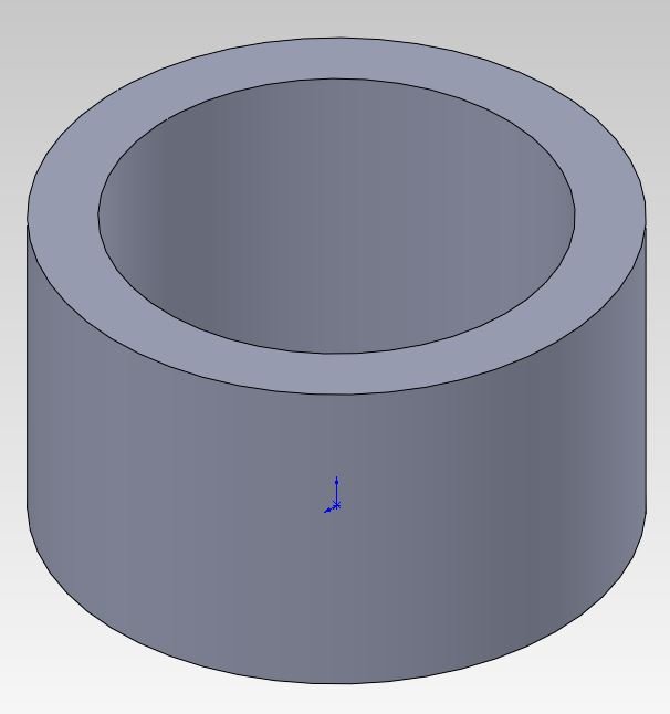
5000fps capture of the Iscar IHRF50 spot facing a test piece of aluminum. Cutting conditions: D=2.75” Fz=0.0027” N=2500rpm
First let’s consider the case for a single point cutting tool as shown above. In the ideal scenario of an infinitely rigid machine and tool, and a control system which responds instantaneously.
The amount of revolutions needed to “clean up” a surface is extremely easy:
Where:
N Rev is the number of revolutions required to fully “clean up” a surface
N Tooth is the tool tooth count.
For a single tooth cutter, the number of revolutions required, is one. For the ideal case it’s very easy and straightforward, let’s show that with pictures to drive the ideal case home.


From left to right we see the progression of the cut in a typical drill cycle, feed in, then rapid out. feed per revolutions is greatly exaggerated.
The starting block
One revolution of the cutter feeding to reach the desired depth, shown by the green surface
The cutter rapid feeding out of the cut (while still rotating), shown by the red surface.
The side view of the resulting surface.
So by inspection we find that since the final depth is reached instantaneously (and perfectly) we must rotate from the line section one revolution to “clean up” the surface. And this will hold true for multi-flute tools, that is assuming that all the cutting face are coincident.
Now that’s the ideal scenario, what about the real world?
We’ll take a look at the real world scenario adding complexity as we go. The first thing we will add is timing. Specifically control loop timing.
Most modern CNC machines have millisecond to microsecond control loop timing allowing for precise control of the cutter along a path, as well as rigid tapping and other neat synchronous motion tasks. We will consider a worse case of one millisecond and best case one hundred microsecond to see what the differences are.
Where:
N Rev is the number of revolutions additionally required to fully “clean up” a surface
N Tooth is the tool tooth count.
Omega is the cutter speed in degrees per second
Delta T is the control loop response time.
The control loop response time is doubled in this case because the control needs to respond to when the system reaches the desired depth, and retract when the dwell is complete. This does make the assumption that position and counting tasks happen with the same priority and the same speed which is where YMMV. And this is just an equation I came up with which I think reasonably describes what’s happening, I’m sure a much smarter person has already figured it out more accurately.
Using the demonstration piece, lets plug in some numbers. At 2500rpm it’s 15000 degrees per second, with a control loop response time of 1 millisecond with a single tooth cutter results in 30 degrees additional revolutions required to fully “clean up” a surface. Or it can be applied as a plus or minus 15 degrees error of the cutter position to its actual depth. Which, does sound reasonable, approximately 1.1 revolutions to fully clean up?
With the best case numbers plugged in we get 3 degrees additional revolutions, or plus or minus 1.5 degrees error.
So there can be quite a difference in how much the cutter has to clean up depending on when the control actually responds to the positions.
And this is still considering a perfectly rigid machine and tool and a perfect motion control. We’ll dive in to that next time.