
Creating The Perfect Back Chamfer in Fusion360
Recently I found myself with the issue of needing to chamfer a part feature, but I couldn’t reach it with the traditional chamfering approach.
So I dug into how to get Fusion360 to make back (backside, bottom chamfering, etc.) chamfers. And unfortunately, it’s not simple or straight forward. And in all honesty, the information seems to be stagnant out there. The best resource for Fusion 360 I’ve found has been NYC CNC, great guys and very informative content. They have a great, although dated, video ( https://youtu.be/HsBR2_6h4mM ) of how they have tackled the problem of back side chamfering if you want to see where I am starting from.
Let’s dive in.

The part in question
This is a two operation part, and has a lot of chamfering challenges.
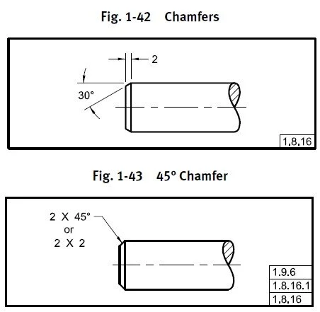
Just for clarity I will be using the ASME Y14.5 standard (section 1.8.16) for chamfer dimensioning. That is, where the called out dimension is the opposite or adjacent side of a triangular chamfer, and not the hypotenuse.
First challenge is finding a backside chamfering tool which fits your part and has adequate reach. I am using Iscar’s MultiMaster upper and bottom chamfering tools (MM HDF100-090-2T05). You can use whatever tool you want, but check the following:
The cutting diameter (DCX) must be smaller than your clearance hole
The cutting diameter (DCX) and the shank diameter (DCONMS) must be smaller than the minimum cutting radius
The back cutting length (L6) must be larger than your desired chamfer size

Whatever tool you’re using you need to bring it into Fusion360. Iscar makes it very easy as they have files package for every tool. If your tool of choice doesn’t have a 2D file, you can always draw it from scratch using provided dimensions. You can also setup a parametric template to use in the future if you’re so inclined.
We want to make a form tool which matches the geometry of your selected tool, here are the steps:
Create a new part
If you’re using a tool manufacturers’ drawing, select “insert” then “DXF” and select the plane you want to insert on.
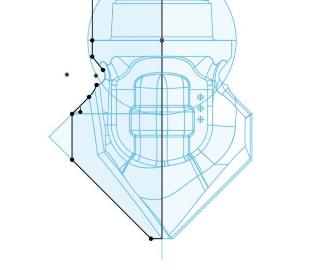
On the same plane, create a new sketch and draw out HALF of the tool’s profile with the sketch origin being on the tool’s centerline.
Now here is the clever bit, to get Fusion to recognize the tool as a back chamfer tool we need to define the tool compensation point. Normally, this point is the revolves centerline at the lowest Z height. But we don’t want that so we need to tell Fusion where we want to compensate the tool point.
Create two construction lines of the L6 area of the tool and make a right angle triangle.
Define length and width as equal
Dimension one line as the length of the desired chamfer.
Iscar MM HDF100-090-2T05
Showing the Iscar tool sketch with another sketch overlaid

Make two construction lines to create the tool compensation point.
Doing the above gives us the compensation point for Fusion and gives us a consistent chamfer dimension.
When we create the form tool we select the tool profile we created, select the axis of rotation (arrow points down), and most importantly select the compensation point we just created. And that’s it! The new form tool is in your tool library.
This is where this method really shines, when we use our new form tool and create a 2D contour or Trace or pocket for chamfering we don’t need to apply any hacky work arounds in the “stock to leave” box or play with the contour height selection, or even need to make a template tool path, it just works! Select the 2D or 3D contour that requires a chamfer and you’re good.
Some caveats however, if your tool diameter is very close to the minimum cutting radius be sure to use feed optimization option. If your tool diameter is also close to the minimum cutting radius, avoid steep Z height changes along 3D contours. You get a “step” in the tool path and may cause gouging. Additionally, if the solid model has the chamfers modeled in, you’ll need to create another form tool with the compensation point at the lower cutting edge.
Here is a quick example of using the back chamfer tool. Very quick and easy